Hardware Installation Guide
This guide provides step-by-step instructions for assembling the SenseEdge Development Kit.
Safety Precautions
Before installation, ensure the power adapter is disconnected from the carrier board.
- Power Off: Never install or remove any components while the system is powered on to prevent hardware damage.
- Static Electricity: Handle all electronic components by their edges to avoid Electrostatic Discharge (ESD).
- Sharp Edges: The cooling fins on the heat sink are sharp. Handle with care during assembly or disassembly to avoid injury.
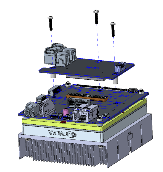
1. Install the GMSL Adapter Board
Connect the GMSL board to the pre-assembled main unit to enable camera connectivity.
- Align the GMSL board with the connectors on the main carrier board.
- Press down firmly to ensure the connectors are fully seated.
- Secure the board using three screws at the corners.
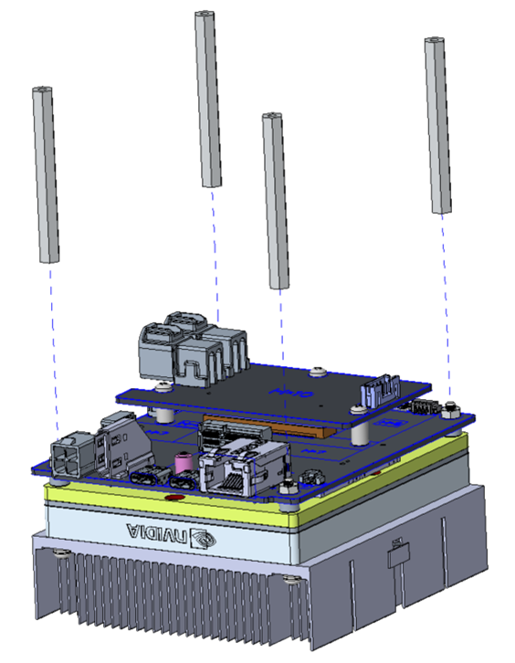
2. Install Support Pillars
Add the pillars to provide stability and clearance for the kit.
- Screw the four support pillars into the mounting holes on the bottom of the board.
- Hand-tighten each pillar until secure.
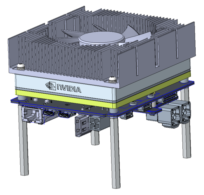
3. Finish
Verify that all components are tightly fastened before moving to the software setup.
Optional: M.2 SSD Installation
The M.2 SSD slot is located on the D317 carrier board, beneath the System on Module (SOM). If you wish to install an SSD, please follow these steps carefully:
- Remove the four long screws (shown in the figure below) that secure the heat sink and SOM.
- Carefully lift and remove the SOM to access the carrier board's SSD slot.
- Caution: Thermal Paste: The bottom of the heat sink has pre-applied thermal paste. Avoid direct skin contact. We recommend wearing gloves or washing your hands immediately if contact occurs. Ensure the paste does not contaminate other electronic components.
- Caution: Sharp Edges: Be careful of the sharp edges on the heat sink fins while handling the module.
- After installing the SSD, re-assemble the SOM and heat sink following the original configuration.
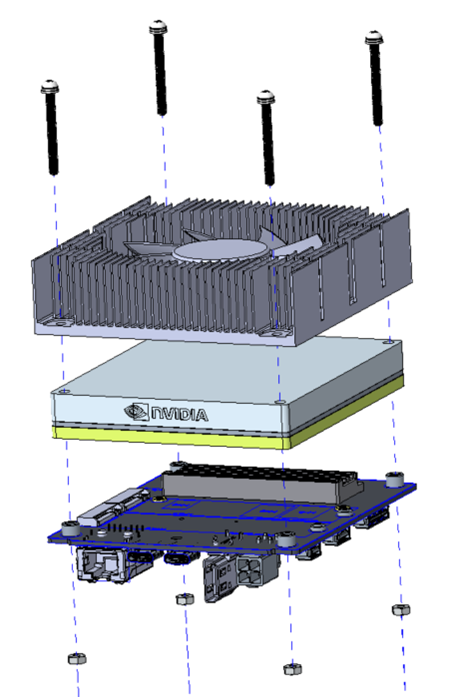
Figure: Remove the four long screws and the SOM to access the SSD slot on the carrier board.
Next Step
After completing the hardware assembly, proceed to the BSP Flashing Guide to set up the system.